|
|
|
|
|
|
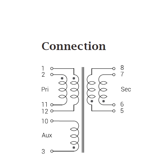
Pri.:Sec.:Aux
|
|
|
|
|
|
|
|
|---|---|---|
|
|
|
|
|
|
|
|
|
|
Pri.:Sec.:Aux
|
|
|
|
|
|
|
|
||
|---|---|---|---|---|---|---|---|---|---|---|---|---|---|---|
|
|
|
|
||||||||||||
| TSP-EFD15S01 | 75 | 67.5 | 8 | 195 | 5 | 195 | 1 : 0.07 : 0.36 | 1.3 | 36 ~ 72 | 1.8 , 3.3 | 6 | 1500 | Flyback | 802.3af Class 0-3 |
| TSP-EFD15S02 | 55 | 49.5 | 4.6 | 95 | 5 | 150 | 1 : 0.08 : 0.36 | 1.2 | 36 ~ 72 | 2.5 , 2.4 | 6 | 1500 | Flyback | 802.3af Class 0-3 |
| TSP-EFD15S03 | 65 | 58.5 | 3.9 | 138 | 7 | 180 | 1 : 0.11: 0.36 | 1.2 | 36 ~ 72 | 3.3 , 1.8 | 6 | 1500 | Flyback | 802.3af Class 0-3 |
| TSP-EFD15S04 | 60 | 54 | 2.3 | 130 | 9 | 165 | 1 : 0.15 : 0.35 | 1.1 | 36 ~ 72 | 5.0 , 1.2 | 6 | 1500 | Flyback | 802.3af Class 0-3 |
| TSP-EFD15S05 | 55 | 49.5 | 0.7 | 95 | 17 | 150 | 1 : 0.35 : 0.35 | 1.1 | 36 ~ 72 | 12 , 0.5 | 6 | 1500 | Flyback | 802.3af Class 0-3 |
| TSP-EFD15S06 | 45 | 40.5 | 7.9 | 195 | 5 | 195 | 1 : 0.07 : 0.36 | 2.3 | 36 ~ 72 | 1.8 , 7.2 | 13 | 1500 | Flyback | 802.3af Class 0-3 |
| TSP-EFD15S07 | 35 | 31.5 | 4.2 | 95 | 5 | 150 | 1 : 0.08 : 0.33 | 2.2 | 36 ~ 72 | 2.5 , 5.2 | 13 | 1500 | Flyback | 802.3af Class 0-3 |
| TSP-EFD15S08 | 40 | 36 | 3.4 | 138 | 7 | 180 | 1 : 0.11 : 0.36 | 2.2 | 36 ~ 72 | 3.3 , 3.9 | 13 | 1500 | Flyback | 802.3af Class 0-3 |
| TSP-EFD15S09 | 40 | 36 | 1.9 | 130 | 9 | 165 | 1 : 0.15 : 0.35 | 2.1 | 36 ~ 72 | 5.0 , 2.6 | 13 | 1500 | Flyback | 802.3af Class 0-3 |
| TSP-EFD15S10 | 35 | 31.5 | 0.6 | 95 | 17 | 150 | 1 : 0.35 : 0.35 | 2 | 36 ~ 72 | 12 , 1.1 | 13 | 1500 | Flyback | 802.3af Class 0-3 |
| TSP-EFD15S11 | 37 | 33.3 | 0.4 | 85 | 25 | 150 | 1 : 0.57 : 0.35 | 2 | 36 ~ 72 | 19.5 , 0.67 | 13 | 1500 | Flyback | 802.3af Class 0-3 |
| TSP-EFD15S12 | 37 | 33.3 | 0.4 | 86 | 49 | 150 | 1 : 0.67 : 0.33 | 2 | 36 ~ 72 | 24 , 0.54 | 13 | 1500 | Flyback | 802.3af Class 0-3 |
Notes:
1. All electrical specifications are referenced to 25°C ± 5°C ambient.
2. The inductance is for the primary, measured at 250 kHz, 0.3 Vrms, 0 ADC.
3. The peak primary current drawn at minimum input voltage.
4. The leakage inductance is for the primary windings with the secondary windings shorted.
5. The DCR for the primary and for the secondary are with the windings connected in parallel.
6. The turns ratios are with the primary the secondary windings connected in parallel.
7. Output is with the secondary windings connected in parallel. Output of the bais winding is 12 V, 20 mA.
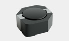
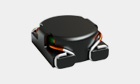
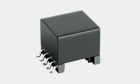
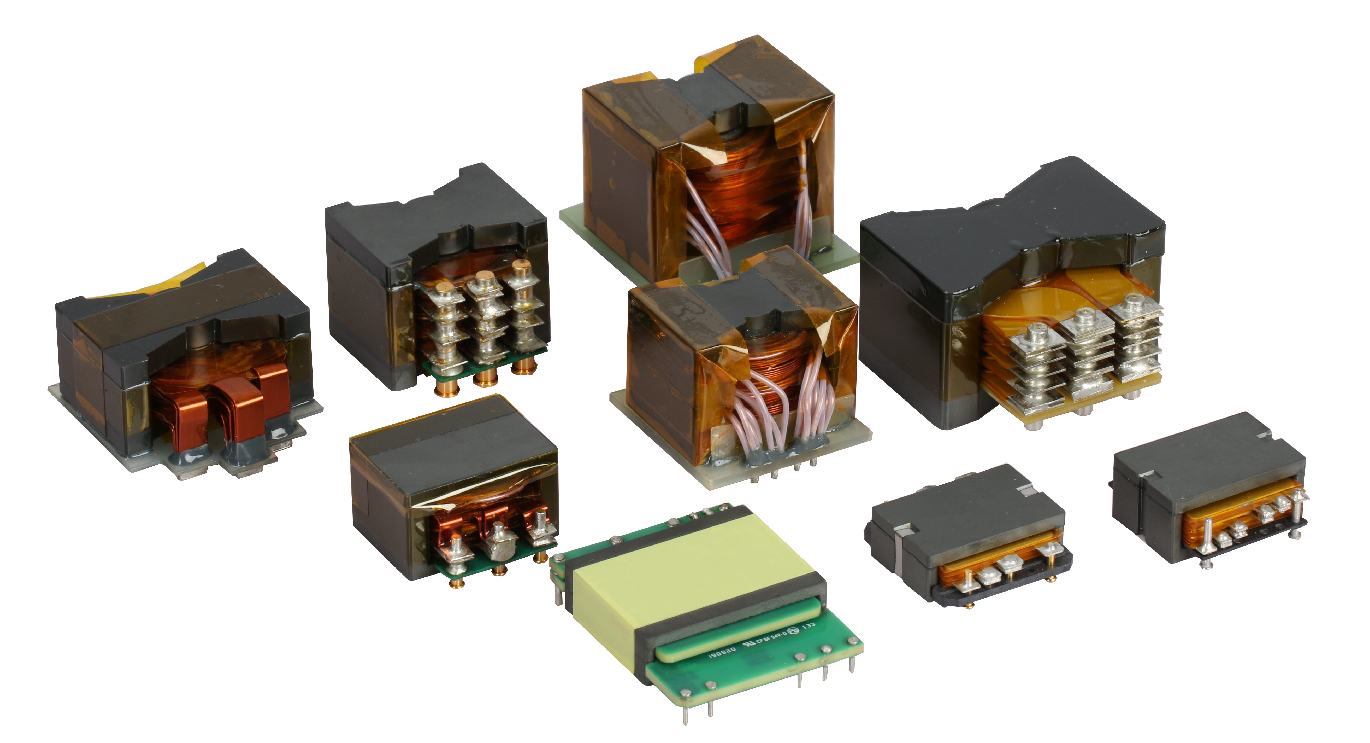
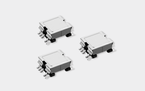
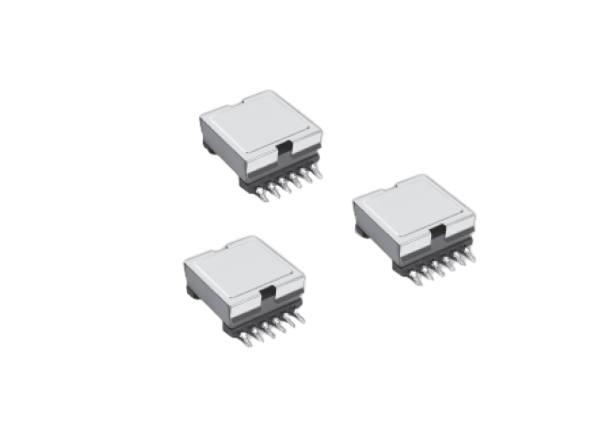
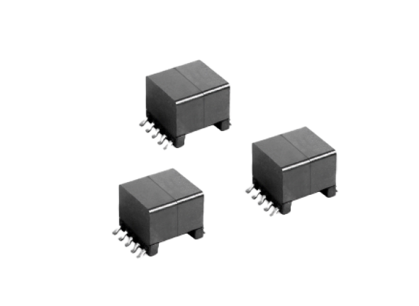
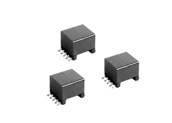
POE Transformer
Read More
➜
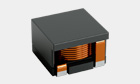
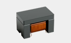
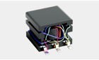
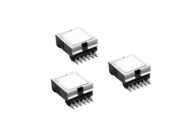
POE Transformer
Read More
➜
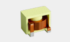
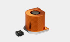
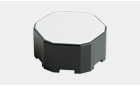
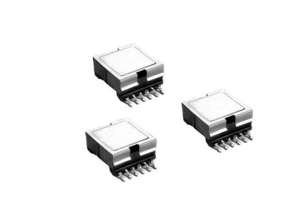
POE Transformer
Read More
➜
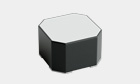
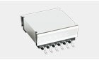
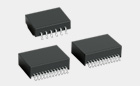
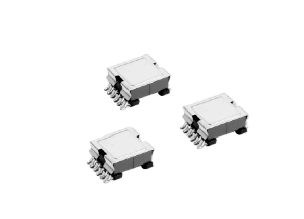
POE Transformer
Read More
➜
POE Transformer
Read More
➜
POE Transformer
Read More
➜
POE Transformer
Read More
➜
POE Transformer
Read More
➜
POE Transformer
Read More
➜
POE Transformer
Read More
➜
POE Transformer
Read More
➜
POE Transformer
Read More
➜

Service Tel
(86-28) 86082899-2805
Copyright © 2026 ZG Tianxin. All Rights Reserved. 蜀ICP备2023041398号-1